Chapter 4: Physical Interrupt Handling and Prioritization
This chapter describes the fundamental aspects of GIC interrupt handling and prioritization. It contains the following sections:
-
Interrupt lifecycle.
-
Locality-specific Peripheral Interrupts.
-
Private Peripheral Interrupts.
-
Software Generated Interrupts.
-
Shared Peripheral Interrupts.
-
Interrupt grouping.
-
Enabling the distribution of interrupts.
-
Interrupt prioritization.
4.1 Interrupt lifecycle
GIC interrupt handling is based on the GIC interrupt lifecycle, a series of high-level processes that apply to any interrupt using the GIC architecture. The interrupt lifecycle provides a basis for describing the detailed steps of the interrupt handling process. The GIC also maintains a state machine that controls interrupt state transitions during the lifecycle.
Figure 4-1 shows the GIC interrupt lifecycle for physical interrupts.
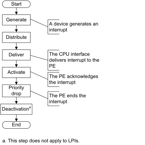
Image text
Start
Generate
A device generates an
interrupt
Distribute
Deliver The CPU interface
delivers interrupt to the
PE
Activate
The PE acknowledges
the interrupt
Priority
drop The PE ends the
interrupt
Deactivation [a]
End
a. This step does not apply to LPIs.
-
Generate interrupt. An interrupt is generated either by the peripheral or by software.
-
Distribute. The IRI performs interrupt grouping, interrupt prioritization, and controls the forwarding of interrupts to the CPU interfaces.
-
Deliver. A physical CPU interface delivers interrupts to the corresponding PE.
-
Activate. When software running on a PE acknowledges an interrupt, the GIC sets the highest active priority to that of the activated interrupt, and for SPIs, SGIs, and PPIs the interrupt becomes active.
-
Priority drop. Software running on the PE signals to the GIC that the highest priority interrupt has been handled to the point where the running priority can be dropped. The running priority then has the value that it had before the interrupt was acknowledged. This is the point where the end of interrupt is indicated by the interrupt handler. The end of the interrupt can be configured to also perform deactivation of the interrupt.
-
Deactivation. Deactivation clears the active state of the interrupt, and thereby allows the interrupt, when it is pending, to be taken again. Deactivation is not required for LPIs. Deactivation can be configured to occur at the same time as the priority drop, or it can be configured to occur later as the result of an explicit interrupt deactivation operation. This latter approach allows for software architectures where there is an advantage to separating interrupt handling into initial handling and scheduled handling.
4.1.1 Physical CPU interface
A CPU interface provides an interface to a PE that is connected to the GIC. Each CPU interface is connected to a single PE. A CPU interface receives pending interrupts prioritized by the IRI, and determines whether the interrupt is a member of a group that is enabled in the CPU interface and has sufficient priority to be signaled to the PE. At any time, the connected PE can determine the:
-
INTID of its highest priority pending interrupt, by reading ICC_HPPIR0_EL1 or ICC_HPPIR1_EL1.
-
The running priority of the CPU interface by reading ICC_RPR_EL1.
Note
The priority of the highest priority active interrupt for which there has not been a priority drop is also known as the running priority.
When an LPI is acknowledged, the pending state for the interrupt changes to not pending in the Redistributor. The Redistributor does not maintain an active state for LPIs.
When the PE acknowledges an SGI, a PPI, or an SPI at the CPU interface, the IRI changes the status of the interrupt to active if:
-
It is an edge-triggered interrupt, and another edge has not been detected since the interrupt was acknowledged.
-
It is a level-sensitive interrupt, and the level has been deasserted since the interrupt was acknowledged.
When the PE acknowledges an SGI, a PPI, or an SPI at the CPU interface, the IRI changes the status of the interrupt to active and pending if:
-
It is an edge-triggered interrupt, and another edge has been detected since the interrupt was acknowledged.
-
It is a level-sensitive interrupt, and the level has not been deasserted since the interrupt was acknowledged.
When the PE acknowledges an SGI, a PPI, or an SPI at the CPU interface, the CPU interface can signal another interrupt to the PE, to preempt interrupts that are active on the PE. If there is no pending interrupt with sufficient priority to be signaled to the PE, the interface deasserts the interrupt request signal to the PE.
The following stages of the interrupt lifecycle are described in the remainder of this section:
-
Activation .
-
Priority drop.
-
Deactivation.
The priority drop and deactivation can be performed as a single operation or can be split, as defined by ICC_CTLR_EL1.EOImode and ICC_CTLR_EL3.EOImode_EL3.
Activation
The interrupt handler reads ICC_IAR0_EL1 for Group 0 interrupts, and ICC_IAR1_EL1 for Group 1 interrupts, in the corresponding CPU interface to acknowledge the interrupt. This read returns either:
-
The INTID of the highest priority pending interrupt, if that interrupt is of sufficient priority for it to be signaled to the PE. This is the normal response to an interrupt acknowledge.
-
Under certain conditions, an INTID that indicates a special interrupt number, see INTIDs.
Whether a read of ICC_IAR0_EL1 and ICC_IAR1_EL1 returns a valid INTID depends on:
-
Which of the two registers is accessed.
-
The Security state of the PE.
-
Whether there is a pending interrupt of sufficient priority to be signaled to the PE, and if so, whether:
-
The highest priority pending interrupt is a Secure Group 1 or a Non-secure Group 1 interrupt.
-
Interrupt signaling is enabled for that interrupt group.
-
-
The Exception level at which the PE is executing.
All interrupts, when acknowledged, modify the Active Priorities Registers . See System register access to the Active Priorities registers. 4.1 Interrupt lifecycle
In certain circumstances, the value of SCR_EL3.NS affects the value returned when a PE acknowledges an interrupt. That is, when the PE is executing at EL3, a Secure read of ICC_IAR0_EL1 returns a special interrupt number that indicates the required Security state transition for the highest priority pending interrupt. Otherwise, the INTID is returned.
For SGIs in a multiprocessor implementation, the GIC uses the targeted list model, where the acknowledgement of an interrupt by one PE has no effect on the state of the interrupt on other CPU interfaces. When a PE acknowledges the interrupt, the pending state of the interrupt is cleared only for that PE. The interrupt remains pending for the other PEs.
The effects of reading ICC_IAR0_EL1 and ICC_IAR1_EL1 on the state of a returned INTID are not guaranteed to be visible until after the execution of a DSB.
Priority drop
After an interrupt has been acknowledged, a valid write to ICC_EOIR0_EL1 for Group 0 interrupts, or a valid write to ICC_EOIR1_EL1 for Group 1 interrupts, results in a priority drop.
A valid write to ICC_EOIR0_EL1 or ICC_EOIR1_EL1 to perform a priority drop is required for each acknowledged interrupt, even for LPIs which do not have an active state. A priority drop must be performed by the same PE that activated the interrupt.
Note A valid write is a write that is:
-
Not UNPREDICTABLE.
-
Not ignored.
-
Not writing an INTID that is either unsupported or within the range 1020-1023.
For each CPU interface, the GIC architecture requires the order of the valid writes to ICC_EOIR0_EL1 and ICC_EOIR1_EL1 to be the exact reverse of the order of the reads from ICC_IAR0_EL1 and ICC_IAR1_EL1, as shown in Figure 4-2.
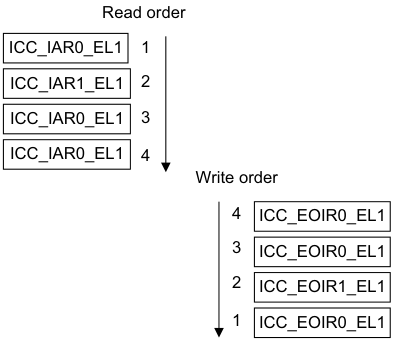
Image text
Read order
ICC_IAR0_EL1 1
ICC_IAR1_EL1 2
ICC_IAR0_EL1 3
ICC_IAR0_EL1 4
Write order
4 ICC_EOIR0_EL1
3 ICC_EOIR0_EL1
2 ICC_EOIR1_EL1
1 ICC_EOIR0_EL1
-
The priority of the highest-priority active interrupt for which there has been no write to ICC_EOIR0_EL1 or ICC_EOIR1_EL1.
-
The idle priority, 0xFF, if there is no active interrupt.
Note For compatibility with possible extensions to the GIC architecture specification, software must preserve the entire register value read from ICC_IAR0_EL1 and ICC_IAR1_EL1 when it acknowledges the interrupt, and use that entire value for the corresponding write to ICC_EOIR0_EL1 and ICC_EOIR1_EL1 by the same PE.
When GICD_CTLR.DS == 0:
-
A write to ICC_EOIR0_EL1 performs a priority drop for Group 0 interrupts.
-
A write to ICC_EOIR1_EL1 performs a priority drop for Non-secure Group 1 interrupts, if the PE is operating in Non-secure state or at EL3.
-
When operating in Secure state, a write to ICC_EOIR1_EL1 performs a priority drop for Secure Group 1 interrupts.
When GICD_CTLR.DS == 1:
-
A write to ICC_EOIR0_EL1 performs a priority drop for Group 0 interrupts.
-
A write to ICC_EOIR1_EL1 performs a priority drop for Group 1 interrupts.
Deactivation
PPIs, SGIs, and SPIs have an active state in the IRI and must be deactivated.
SGIs and PPIs must be deactivated by the PE that activated the interrupt. SPIs can be deactivated by a different PE.
Interrupt deactivation is required to change the state of an interrupt either:
-
From active and pending to pending.
-
From active to inactive.
Depending on the Exception level and Security state, ICC_CTLR_EL1.EOImode and
ICC_CTLR_EL3.EOImode_EL3 in the appropriate CPU Interface Control Register determine whether priority drop and interrupt deactivation happen together or separately:
-
The priority drop and interrupt deactivation happen together when ICC_CTLR_EL1.EOImode or ICC_CTLR_EL3.EOImode_EL3 in the CPU interface is 0, and the PE writes to ICC_EOIR0_EL1 or ICC_EOIR1_EL1. In this case a write to ICC_DIR_EL1 is not required.
-
The priority drop and interrupt deactivation are separated when ICC_CTLR_EL1.EOImode or ICC_CTLR_EL3.EOImode_EL3 in the CPU interface is 1, and the PE writes to ICC_EOIR0_EL1 or ICC_EOIR1_EL1. In this case:
-
The priority drop happens when the PE writes to ICC_EOIR0_EL1 or ICC_EOIR1_EL1.
-
Interrupt deactivation happens later, when the PE writes to ICC_DIR_EL1. A valid write to ICC_DIR_EL1 results in interrupt deactivation for a Group 0 or a Group 1 interrupt.
-
There are no ordering requirements for writes to ICC_DIR_EL1. If software writes to ICC_DIR_EL1 when the following conditions are true, the results are unpredictable:
-
The appropriate EOIMode bit is cleared to 0.
-
The ICC_CTLR_EL1.EOImode or ICC_CTLR_EL3.EOIMode_EL3 is set to 1 and there has not been a corresponding write to ICC_EOIR0_EL1 or ICC_EOIR1_EL1.
When ICC_CTLR_EL1.EOImode or ICC_CTLR_EL3.EOIMode_EL3 == 1 but the interrupt is not active in the Distributor, writes to ICC_DIR_EL1 must be ignored. If supported, an implementation might generate a system error. Table 4-1 shows how a write to ICC_EOIR0_EL1 or ICC_EOIR1_EL1 affects deactivation.
Table 4-1 Effect of writing to ICC_EOIR0_EL1 or ICC_EOIR1_EL1
| Access | ICC_CTLR_EL1.EOImode or ICC_CTLR_EL3.EOImode_EL3 | Identified interrupt | Effect |
|---|---|---|---|
| ICC_EOIR1_EL1 | 0 | Group 0 | Access ignored |
| ICC_EOIR0_EL1 | 0 | Group 0 | Interrupt deactivated |
| ICC_EOIR1_EL1 | 0 | Group 1 | Interrupt deactivated |
| ICC_EOIR0_EL1 | 0 | Group 1 | Access ignored |
| - | 1 | - | Interrupt remains active |
When GICD_CTLR.DS == 0, access to certain registers is restricted. See Interrupt grouping and security.
The following pseudocode determines whether EOImode is set for the current Exception level and Security state:
// EOImodeSet()
// ============

boolean EOImodeSet()

     if HaveEL(EL3) then
         // EL3 is implemented so return the value appropriate to the EL and security state
         if IsEL3OrMon() && ICC_SRE_EL3.SRE == '1'1 then
             // In EL3
             EOImode = ICC_CTLR_EL3.EOImode_EL3;

         elsif IsSecure() then
             EOImode = ICC_CTLR_EL3.EOImode_EL1S;

         else                                                  // Non-secure
              EOImode = ICC_CTLR_EL3.EOImode_EL1NS;
     else
         // No EL3 so return the value from ICC_CTLR_EL1
         EOImode = ICC_CTLR_EL1.EOImode;

     return EOImode == '1';
Effect of Security states on writes to ICC_DIR_EL1
The effect of a write to ICC_DIR_EL1 depends on whether the GIC supports one or two Security states:
-
If GICD_CTLR.DS == 0, a valid:
- Secure write to ICC_DIR_EL1 deactivates the specified interrupt, regardless of whether that interrupt is a Group 0 or a Group 1 interrupt.- Non-secure write to ICC_DIR_EL1 deactivates the specified interrupt only if that interrupt is a Non-secure Group 1 interrupt.
-
If GICD_CTLR.DS == 1, a valid write to ICC_DIR_EL1 deactivates the specified interrupt, regardless of whether that interrupt is a Group 0 or Group 1 interrupt. Table 4-2 shows the behavior of valid writes to ICC_DIR_EL1. In an implementation that supports only a single Security state, valid writes have the behavior shown for Secure writes to ICC_DIR_EL1.
Table 4-2 Behavior of writes to ICC_DIR_EL1
| Security state and Exception level of writes to ICC_DIR_EL1 | Interrupt group | GICD_CTLR.DS | SCR_EL3.IRQ | SCR_EL3.FIQ | Effect |
|---|---|---|---|---|---|
| EL3 | x | x | x | x | Interrupt is deactivated |
| Secure EL1 or Secure EL2 | Group 0 | x | x | 0 | Interrupt is deactivated |
| Secure EL1 or Secure EL2 | Group 0 | x | x | 1 | Write is ignored |
| Secure EL1 or Secure EL2 | Group 1 | x | 0 | x | Interrupt is deactivated |
| Secure EL1 or Secure EL2 | Group 1 | x | 1 | x | Write is ignored |
| EL2 or Non-secure EL1 | Group 0 or Secure Group 1 | 0 | x | x | Write is ignored |
| EL2 or Non-secure EL1 | Group 0 | 1 | x | 0 | Interrupt is deactivated |
| EL2 or Non-secure EL1 | Group 0 | 1 | x | 1 | Write is ignored |
| EL2 or Non-secure EL1 | Non-secure Group 1 | 0 | 0 | x | Interrupt is deactivated |
| EL2 or Non-secure EL1 | Non-secure Group 1 | 0 | 1 | x | Write is ignored |
| EL2 or Non-secure EL1 | Group 1 | 1 | 0 | x | Interrupt is deactivated |
| EL2 or Non-secure EL1 | Group 1 | 1 | 1 | x | Write is ignored |
Secure EL2 can only be entered when SCR_EL3.EEL2 == 1.
4.1.2 Interrupt handling state machine
The GIC maintains a state machine for each supported interrupt. The possible states of an interrupt are:
-
Inactive.
-
Pending.
-
Active.
-
Active and pending.
PPIs, SGIs, and SPIs can have an active and pending state. Interrupts that are active and pending are never signaled to a connected PE. LPIs have a pending state that is held in memory associated with a Redistributor, and therefore a PE. This also applies to directly injected virtual LPIs, see About GICv4.0 virtual Locality-specific Peripheral Interrupt support.
Note There is no active or active and pending state for LPIs.
Figure 4-3 shows an instance of the interrupt handling state machine, and the possible state transitions.
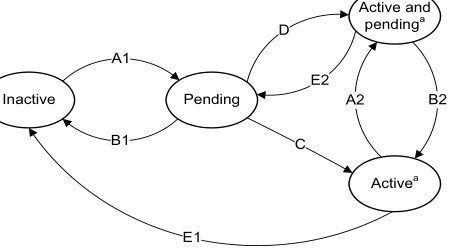
Image text
Active and
D pending [a]
A1
E2
Inactive Pending A2 B2
B1 C
Active [a]
E1
a. Not applicable for SGIs when GICD_CTLR.nASSGIreq==1,
and for LPIs.
Figure 4-3 Interrupt handling state machine
Note LPIs do not have an active state in the Redistributor, but do require an active priority in the CPU interface. See Chapter 5 Locality-specific Peripheral Interrupts and the ITS for more information.
Arm expects hardware implementations to report GICD_TYPER2.nASSGIcap==0, indicating that GICD_CTLR.nASSGIreq is RES0.
When interrupt forwarding by the Distributor and interrupt signaling by the CPU interface are enabled, the conditions that cause each of the state transitions are as follows:
Transition A1 or A2, add pending state
This transition occurs when the interrupt becomes pending, either as a result of the peripheral generating the interrupt or as result of software generating the interrupt.
Transition B1 or B2, remove pending state
This transition occurs when the interrupt has been deasserted by the peripheral, if the interrupt is a level-sensitive interrupt, or when software has changed the pending state.
For LPIs, it also occurs on acknowledgement of the interrupt.
Transition C, pending to active
This transition occurs on acknowledgement of the interrupt by the PE for edge-triggered SPIs, SGIs, and PPIs.
For SPIs, SGIs, and PPIs, this transition occurs when software reads an INTID value from ICC_IAR0_EL1 or ICC_IAR1_EL1.
Transition D, pending to active and pending
This transition occurs on acknowledgement of the interrupt by the PE for level-sensitive SPIs, SGIs, and PPIs.
Transition E1 or E2, remove active state
This transition occurs when software deactivates an interrupt for SPIs, SGIs, and PPIs.
4.2 Locality-specific Peripheral Interrupts
LPIs are targeted peripheral interrupts that are routed to a specific PE within the affinity hierarchy. In a system where two Security states are enabled, LPIs are always Non-secure Group 1 interrupts. LPIs only support edge-triggered behavior. For more information about LPIs, see LPIs.
4.3 Private Peripheral Interrupts
PPIs are interrupts that target a single, specific PE, and different PEs can use the same INTID to indicate different events. PPIs can be Group 0 interrupts, Secure Group 1 interrupts, or Non-secure Group 1 interrupts. They can support either edge-triggered or level-sensitive behavior.
An optional extended PPI range uses INTIDs 1056 - 1119. This range of PPIs is not available when the GIC is operating in legacy mode. GICR_TYPER.PPInum indicates whether the extended PPI range is supported or not.
Note Commonly, Arm expects that PPIs are used by different instances of the same interrupt source on each PE, thereby allowing a common INTID to be used for PE specific events, such as the interrupts from a private timer.
4.4 Software Generated Interrupts
SGIs are typically used for inter-processor communication, and are generated by a write to an SGI register in the GIC. SGIs can be either Group 0 or Group 1 interrupts, and they can support only edge-triggered behavior.
The registers associated with the generation of SGIs are part of the CPU interface:
-
A PE generates a Group 1 SGI by writing to ICC_SGI1R_EL1 or ICC_ASGI1R_EL1.
-
A PE generates a Group 0 SGI by writing to ICC_SGI0R_EL1.
-
Routing information is supplied as the bitfield value in the write to the register that generated the SGI. The SGI can be routed to:
-
The group of PEs specified by a.b.c.targetlist. This can include the originating PE.
-
All participating PEs in the system, excluding the originating PE.
-
See Routing SPIs and SGIs by PE affinity for more information.
ICC_SGI1R_EL1 allows software executing in a Secure state to generate Secure Group 1 SGIs.
ICC_SGI1R_EL1 allows software executing in a Non-secure state to generate Non-secure Group 1 SGIs.
ICC_ASGI1R_EL1 allows software executing in a Secure state to generate Non-secure Group 1 SGIs.
ICC_ASGI1R_EL1 allows software executing in a Non-secure state to generate Secure Group 1 SGIs, if permitted by the settings of GICR_NSACR in the Redistributor corresponding to the target PE.
ICC_SGI0R_EL1 allows software executing in Secure state to generate Group 0 SGIs.
ICC_SGI0R_EL1 allows software executing in Non-secure state to generate Group 0 SGIs, if permitted by the settings of GICR_NSACR in the Redistributor corresponding to the target PE.
For more information about the use of control registers to forward SGIs to a target PE, see Table 12-14.
4.5 Shared Peripheral Interrupts
SPIs are peripheral interrupts that the Distributor can route to a specified PE that can handle the interrupt, or to a PE that is one of a group of PEs in the system that has been configured to accept this type of interrupt. SPIs can be either Group 0 or Group 1 interrupts, and they can support either edge-triggered or level-sensitive behavior.
An optional extended SPI range uses INTIDs 4096 - 5119. This range of SPIs is not available when the GIC is operating in legacy mode. GICD_TYPER.ESPI indicates whether the extended SPI range is supported or not.
SPIs can be either wired-based or message-based interrupts.
Support for message-based SPIs is optional, and can be discovered through GICD_TYPER.MBIS. Message-based SPIs can be:
-
Generated by a write to GICD_SETSPI_NSR or GICD_SETSPI_SR
-
Cleared by a write to GICD_CLRSPI_NSR or GICD_CLRSPI_SR.
The effect of a write to these registers depends on whether the targeted SPI is configured to be an edge-triggered or a level-sensitive interrupt:
-
For an edge-triggered interrupt, a write to GICD_SETSPI_NSR or GICD_SETSPI_SR sets the interrupt pending. The interrupt is no longer pending when it is activated, or when it is cleared by a write to GICD_CLRSPI_NSR, GICD_CLRSPI_SR, or GICD_ICPENDR
. -
For a level-sensitive interrupt, a write to GICD_SETSPI_NSR or GICD_SETSPI_SR sets the interrupt pending. It remains pending until it is deasserted by a write to GICD_CLRSPI_NSR or GICD_CLRSPI_SR. If the interrupt is activated between the time it is asserted by a write to GICD_SETSPI_NSR or GICD_SETSPI_SR and the time it is deactivated by a write to GICD_CLRSPI_NSR or GICD_CLRSPI_SR, then the interrupt becomes active and pending.
-
It is IMPLEMENTATION DEFINED for a level-sensitive interrupt whether a write to GICD_ICPENDR
has any effect on an interrupt that has been set pending by a write to GICD_SETSPI_NSR or GICD_SETSPI_SR, or whether a write to GICD_CLRSPI_NSR or GICD_CLRSPI_SR has any effect on an interrupt that has been set pending by a write GICD_ISPENDR . -
It is IMPLEMENTATION DEFINED whether acknowledging an interrupt that was set pending by a write to GICD_ISPENDR
clears the pending state.
-
-
Changing the configuration of an interrupt from level-sensitive to edge-triggered, or from edge-triggered to level-sensitive, when there is a pending interrupt, leaves the interrupt in an UNKNOWN state.
Figure 4-4 shows how message-based interrupt requests can trigger SPIs.
| Wire-based | Wire-based | Wire-based | Wire-based | Wire-based | Wire-based | SPIs | SPIs | SPIs | ||||||||||||||||||||||||
|---|---|---|---|---|---|---|---|---|---|---|---|---|---|---|---|---|---|---|---|---|---|---|---|---|---|---|---|---|---|---|---|---|
| Message- | Distributor | |||||||||||||||||||||||||||||||
| based SPIs | GICD_SETSPI_SR registers | GICD_SETSPI_NSR | registers | |||||||||||||||||||||||||||||
| GICD_CLRSPI_SR registers | GICD_CLRSPI_NSR | registers | ||||||||||||||||||||||||||||||
| x.y.0.0 | PE Redistributor | Cluster C0 | x.y.0.1 | PE | x.y.0.2 | PE | CPU interface | x.y.n.0 | PE | Cluster | PE x.y.n.1 Cn |
Figure 4-4 Triggering SPIs
4.6 Interrupt grouping
GICv3 uses interrupt grouping as a mechanism to align interrupt handling with the Armv8 Exception model and Security model.
In a system with two Security states, an interrupt is configured as one of the following:
-
A Group 0 physical interrupt:
- Arm expects these interrupts to be handled at EL3.
-
A Secure Group 1 physical interrupt:
- Arm expects these interrupts to be handled at Secure EL1 or Secure EL2 in a system using Secure virtualization.
-
A Non-secure Group 1 physical interrupt:
- Arm expects these interrupts to be handled at Non-secure EL2 in systems using virtualization, or at Non-secure EL1 in systems not using virtualization.
In a system with one Security state an interrupt is configured to be either:
-
Group 0.
-
Group 1.
At the System level, GICD_CTLR.DS indicates if the GIC is configured with one or two Security states. For more information about Security, see Interrupt grouping and security.
These interrupt groups are mapped onto the Armv8 FIQ and IRQ exceptions, see Interrupt assignment to IRQ and FIQ signals.
GICD_IGROUPR
GICR_IGROUPR0 and GICR_IGRPMODR0 configure the interrupt group for SGIs and PPIs, and GICR_IGROUPR
Note
When GICD_CTLR.DS == 0, LPIs are always Non-secure Group 1 interrupts. When GICD_CTLR.DS == 1, LPIs are always Group 1 interrupts.
System registers control and configure Group 0 and Group 1 interrupts:
-
For Group 0 interrupts, software uses: — ICC_IAR0_EL1 to read a Group 0 INTID on an interrupt acknowledge.
-
ICC_EOIR0_EL1 to write a Group 0 interrupt completion.
-
ICC_BPR0_EL1 to configure the binary point for Group 0 prioritization. This register is also used for Group 1 prioritization when ICC_CTLR_EL1.CBPR == 1.
-
ICC_HPPIR0_EL1 to read the highest Group 0 interrupt that is currently pending.
-
ICC_IGRPEN0_EL1 to enable Group 0 interrupts at the CPU interface.
-
-
For Group 1 interrupts, software uses:
-
ICC_IAR1_EL1 to read a Group 1 INTID on an interrupt acknowledge.
-
ICC_EOIR1_EL1 to write a Group 1 interrupt completion.
-
ICC_BPR1_EL1 to configure the binary point for Group 1 prioritization for the current Security state.
-
ICC_HPPIR1_EL1 to read the highest Group 1 interrupt that is currently pending.
-
ICC_IGRPEN1_EL1 to enable Group 1 interrupts for the target Security state of the interrupt.
-
In a system with two Security states, Group 0 interrupts are always Secure. For more information about grouping and Security, see Interrupt grouping and security.
4.6.1 Interrupt grouping and security
The Arm architecture provides two Security states, each with an associated physical memory address space:
-
Secure state.
-
Non-secure state.
A software hierarchy of user and privileged code can execute in either state, and software executing in Non-secure state can only access Secure state through a system call to the Secure monitor. The GIC architecture supports the routing and handling of interrupts associated with both Security states.
GICD_CTLR.DS indicates whether a GIC is configured to support the Armv8-A Security model. This configuration affects:
-
Register access, see GIC System register access.
-
The interrupt groups that are supported.
When GICD_CTLR.DS == 0:
-
The GIC supports two Security states, Secure state and Non-secure state.
-
The GIC supports three interrupt groups:
- Group 0. - Secure Group 1.- Non-secure Group 1.
-
Both the Security state and GICR_NSACR determine whether an SGI can be generated.
-
The Security state is checked during:
- Configuration of an interrupt. - Acknowledgement of an interrupt.-
Priority drop.
-
Deactivation.
-
-
Secure Group 1 interrupts are treated as Group 0 by a CPU interface if:
-
The PE does not implement EL3.
-
ICC_SRE_EL1(S).SRE == 0.
-
When GICD_CTLR.DS == 1:
-
The GIC supports only a single Security state. This can be either Secure state or Non-secure state.
-
The GIC supports two interrupt groups:
-
Group 0.
-
Group 1.
-
-
SGIs can be generated regardless of the settings in GICR_NSACR.
-
The Security state is not checked during:
-
Configuration of an interrupt.
-
Acknowledgement of an interrupt.
-
Priority drop.
-
-
Deactivation.
In a multiprocessor system, one or more PEs within the system might support accesses to resources that are available only in Secure state, or accesses to resources that are available only in Non-secure state. It is a programming error if software configures:
-
A Group 0 or Secure Group1 interrupt to be forwarded to a PE that only supports Non-secure state.
-
A Non-secure Group1 interrupt to be forwarded to a PE that only supports Secure state.
There is a dedicated register for the priority grouping for each interrupt group, ICC_BPR0_EL1 for Group 0 interrupts and ICC_BPR1_EL1 for Group 1 interrupts. However, it is possible to configure a common Binary Point Register for both groups using:
-
ICC_CTLR_EL1.CBPR.
-
ICC_CTLR_EL3.CBPR_EL1NS and ICC_CTLR_EL3.CBPR_EL1S for an independent common Binary Point Register configuration of Non-secure Group 1 and Secure Group 1 interrupts. For information about interrupt grouping and legacy operation, see Chapter 14 Legacy Operation and Asymmetric Configurations .
4.6.2 Interrupt assignment to IRQ and FIQ signals
This subsection applies to implementations in which affinity routing is enabled.
A Group 0 physical interrupt, when it is the highest priority pending interrupt and has sufficient priority, is always signaled as an FIQ.
A Group 1 physical interrupt, when it is the highest priority pending interrupt and has sufficient priority, is signaled as an FIQ if either of the following conditions is true, otherwise it is signaled as an IRQ:
-
It is an interrupt for the other Security state, that is, the Security state in which the PE is not executing.
-
• The PE is executing at EL3.
Table 4-3 summarizes the signaling of interrupts when EL3 is using AArch64 state.
Table 4-3 Interrupt signals for two Security states when EL3 is using AArch64 state
| Current Exception level | Group 0 interrupts | Secure Group 1 interrupts | Non-secure Group 1 interrupts |
|---|---|---|---|
| Secure EL1 or EL0 or EL2 | FIQ | IRQ | FIQ |
| Non-secure EL1 or EL0, or Non-secure EL2 | FIQ | FIQ | IRQ |
| EL3 | FIQ | FIQ | FIQ |
Table 4-4 summarizes the signaling of interrupts when EL3 is using AArch32 state. Secure EL2 is not present when EL3 is using AArch32 state.
Table 4-4 Interrupt signals for two Security states when EL3 is using AArch32 state
| Current Exception level | Group 0 interrupts | Secure Group 1 interrupts | Non-secure Group 1 interrupts |
|---|---|---|---|
| Secure EL0 | FIQ | IRQ | FIQ |
| Non-secure EL1 or EL0, or Non-secure EL2 | FIQ | FIQ | IRQ |
| EL3 | FIQ | IRQ | FIQ |
Table 4-5 summarizes the signaling of interrupts in systems that support only a single Security state, that is where EL3 is not implemented or when GICD_CTLR.DS == 1.
Table 4-5 Interrupt signals for a single Security state
| Current Exception level | Group 0 interrupts | Group 1 interrupts |
|---|---|---|
| Any | FIQ | IRQ |
The assertion and de-assertion of IRQs and FIQs are affected by the current Exception level and Security state of the PE. As part of the Context Synchronization that occurs as the result of taking or returning from an exception, the CPU interface ensures that IRQ and FIQ are both appropriately asserted or deasserted for the Exception level and Security state that the PE is entering.
Note For the effects of GICC_CTLR.FIQEn on interrupt signaling in asymmetric configurations, see The asymmetric configuration.
4.6.3 Interrupt routing and System register access
When executing in AArch64 state, interrupt routing to an Exception level is controlled by the following bits:
-
SCR_EL3.FIQ, SCR_EL3.NS, and HCR_EL2.FMO control FIQs.
-
SCR_EL3.IRQ, SCR_EL3.NS, and HCR_EL2.IMO control IRQs.
This routing also controls the Exception level at which the EL1 CPU interface System registers that control and acknowledge interrupts are accessible. This applies to:
-
ICC_IAR0_EL1, ICC_EOIR0_EL1, ICC_HPPIR0_EL1, ICC_BPR0_EL1, ICC_AP0R
_EL1 and ICC_IGRPEN0_EL1. These are the registers that are associated with Group 0 interrupts. -
ICC_IAR1_EL1, ICC_EOIR1_EL1, ICC_HPPIR1_EL1, ICC_BPR1_EL1, ICC_AP1R
_EL1 and ICC_IGRPEN1_EL1. These are the registers that are associated with Group 1 interrupts. -
ICC_SGI0R_EL1, ICC_SGI1R_EL1, ICC_ASGI1R_EL1, ICC_CTLR_EL1, ICC_DIR_EL1, ICC_PMR_EL1, and ICC_RPR_EL1. These are the Common registers.
When (SCR_EL3.NS == 1 || SCR_EL3.EEL2== 1) && (HCR_EL2.FMO ==1 || HCR_EL2.IMO == 1)), accesses at EL1 are virtual accesses. Virtual accesses to ICC_SGI0R_EL1, ICC_SGI1R_EL1, and ICC_ASGI1R_EL1 always generate a Trap exception that is taken to EL2. Where a Distributor supports two Security states a PE might not implement EL2 or EL3. Table 4-6 shows the configurations that are supported in these cases.
Table 4-6 Supported configurations when EL3 is not implemented
| Distributor | EL3 | EL2 | Security State | Description |
|---|---|---|---|---|
| Two Security states, GICD_CTLR.DS == 0 | No | - | Non-secure | The PE is always Non-secure and can only receive Non-secure Group 1 interrupts. The PE must behave as if software had: Set ICC_SRE_EL3.Enable to 1; Set ICC_SRE_EL3.DFB to 1; Set SCR_EL3.FIQ to 1; Cleared SCR_EL3.IRQ to 0; Set SCR_EL3.NS to 1; Cleared ICC_IGRPEN0_EL1.Enable to 0; Set the Secure copy of ICC_IGRPEN1_EL1.Enable to 0. |
| Two Security states, GICD_CTLR.DS == 0 | No | No | Secure | The PE is always Secure and can only receive Group 0 and Secure Group 1 interrupts. The PE must behave as if software had: Set ICC_SRE_EL3.Enable to 1; Cleared SCR_EL3.FIQ to 0; Cleared SCR_EL3.IRQ to 0; Cleared SCR_EL3.NS to 0; Cleared the Non-secure copy of ICC_IGRPEN1_EL1.Enable to 0. |
| One Security state, or two Security states with GICD_CTLR.DS == 1 | No | - | - | The Distributor and all PEs are always in a single Security state, and can receive Group 0 and Group 1 interrupts. All PEs must behave as if software had: Set ICC_SRE_EL3.Enable to 1; Cleared SCR_EL3.FIQ to 0; Cleared SCR_EL3.IRQ to 0; Set SCR_EL3.NS to 1. |
4.7 Enabling the distribution of interrupts
The following control bits enable and disable the distribution of interrupts:
-
GICD_CTLR.EnableGrp1S.
-
GICD_CTLR.EnableGrp1NS.
-
GICD_CTLR.EnableGrp0.
The following control bits enable and disable the distribution of interrupt groups at the CPU interface:
-
ICC_IGRPEN0_EL1.Enable for Group 0 interrupts.
-
ICC_IGRPEN1_EL1.Enable for Group 1 interrupts.
Note
-
There is a Secure and a Non-secure copy of this register.
-
ICC_IGRPEN1_EL3.{EnableGrp1S, EnableGrp1NS}.
Physical LPIs are enabled by a write to GICR_CTLR.EnableLPIs.
4.7.1 Enabling individual interrupts
PPIs
PPIs can be enabled and disabled by writing to GICR_ISENABLER0 and GICR_ICENABLER0 when affinity routing is enabled for the Security state of the interrupt. Individual PPIs can also be enabled and disabled by writing to GICD_ISENABLER
PPIs in the optional, extended PPI range are enabled and disabled by writing to GICR_ISENABLER
SPIs
Individual SPIs can be enabled and disabled by writing to GICD_ISENABLER
SPIs in the optional, extended SPI range are enabled and disabled by writing to GICD_ISENABLER
SGIs
SGIs can be enabled and disabled by writing to GICR_ISENABLER0 and GICR_ICENABLER0 when affinity routing is enabled. Individual SGIs can also be enabled and disabled by writing to GICD_ISENABLER
Note Whether SGIs are permanently enabled, or can be enabled and disabled by writes to GICR_ISENABLER0 and GICR_ICENABLER0, is IMPLEMENTATION DEFINED.
LPIs
Individual LPIs can be enabled by setting the enable bits programmed in the LPI Configuration table. For more information about enabling LPIs using the LPI Configuration tables, see LPI Configuration tables.
4.7.2 Interaction of group and individual interrupt enables
The GICD_* and GICR_* registers determine, at any moment in time, the highest priority pending interrupt that the hardware is aware of for each target PE. This interrupt is presented to the CPU interface of a PE to evaluate whether it is to be signaled to the PE. The enabling of the interrupts affects this evaluation as follows:
-
A pending interrupt that is individually disabled in the GICD_* or GICR_* registers is not one which is considered in the determination of the highest priority pending interrupt, and so cannot be signaled to the PE.
-
A pending interrupt that is individually enabled in the GICD_* or GICR_* registers, but is a member of a group that is disabled in GICD_CTLR, is not one that is considered in the determination of the highest priority pending interrupt, and so cannot be signaled to the PE.
-
A pending 1 of N interrupt that is individually enabled in the GICD_* registers and is a member of a group that is enabled in GICD_CTLR, but is a member of a group that is disabled in ICC_IGRPEN0_EL1, ICC_IGRPEN1_EL1, or ICC_IGRPEN1_EL3 for a PE, cannot be selected for that PE. Such an interrupt is not considered in the determination of the highest priority pending interrupt and so cannot be signaled to the PE.
-
For a pending direct interrupt that is individually enabled in the GICD_* or GICR_* registers and is a member of a group that is enabled in GICD_CTLR, but is a member of a group that is disabled in ICC_IGRPEN0_EL1, ICC_IGRPEN1_EL1, or ICC_IGRPEN1_EL3, it is IMPLEMENTATION DEFINED whether or not the interrupt is considered in the determination of the highest priority pending interrupt. If it is determined to be the highest priority pending interrupt, the interrupt is not signaled to the PE, but will mask a lower priority pending interrupt that is a member of a group that is enabled in ICC_IGRPEN0_EL1, ICC_IGRPEN1_EL1, or ICC_IGRPEN1_EL3.
LPIs are enabled individually in the LPI Configuration tables, see LPI Configuration tables.
4.7.3 Effect of disabling interrupts
Disabling an interrupt by writing to the appropriate GICD_ICENABLER
If GICD_CTLR.EnableGrp0, GICD_CTLR.EnableGrp1S, and GICD_CTLR.EnableGrp1NS are all cleared to 0, it is IMPLEMENTATION DEFINED whether:
-
An edge-triggered interrupt signal moves the interrupt to the pending state.
-
SGIs can be set pending by writing to GICD_SGIR, ICC_SGI0R_EL1, ICC_SGI1R_EL1, or ICC_ASGI1R_EL1.
If an interrupt is pending on a CPU interface when the corresponding GICD_CTLR.EnableGrp0, GICD_CTLR.EnableGrp1NS, or GICD_CTLR.EnableGrp1S bit is written from 1 to 0, then the interrupt must be retrieved from the CPU interface.
Note This might have no effect on the forwarded interrupt if it has already been activated.
If an interrupt is pending on a CPU interface when software writes ICC_IGRPEN0_EL1.Enable, ICC_IGRPEN0_EL1, ICC_IGRPEN1_EL1.Enable, or ICC_IGRPEN1_EL3.Enable from 1 to 0, the interrupt must be released by the CPU interface to allow the Distributor to forward the interrupt to a different PE.
4.8 Interrupt prioritization
This section describes interrupt prioritization in the GIC architecture. Prioritization describes the:
-
Configuration and control of interrupt priority.
-
Order of execution of pending interrupts.
-
Determination of when interrupts are visible to a target PE, including:
-
Interrupt priority masking.
-
Priority grouping.
-
Preemption of an active interrupt.
-
Software configures interrupt prioritization in the GIC by assigning a priority value to each interrupt source. Priority values are an 8-bit unsigned binary number. A GIC implementation that supports two Security states must implement a minimum of 32 and a maximum of 256 levels of physical priority. A GIC implementation that supports only a single Security state must implement a minimum of 16 and a maximum of 256 levels of physical priority. If the GIC implements fewer than 256 priority levels, the low-order bits of the priority fields are RAZ/WI. This means that the number of implemented priority field bits is IMPLEMENTATION DEFINED, in the range 4-8. Table 4-7 shows the relation between the priority field bits and the number of priority levels supported by an implementation.
Table 4-7 Effect of not implementing some priority field bits
| Implemented priority bits | Possible | priority field values | Number of priority levels |
|---|---|---|---|
| [7:0] | 0x00-0xFF | (0-255), all values | 256 |
| [7:1] | 0x00-0xFE, | (0-254), even values only | 128 |
| [7:2] | 0x00-0xFC | (0-252), in steps of 4 | 64 |
| [7:3] | 0x00-0xF8 | (0-248), in steps of 8 | 32 |
| [7:4] | 0x00-0xF0 | (0-240), in steps of 16 | 16 |
In the GIC prioritization scheme, lower numbers have higher priority. This means that the lower the assigned priority value, the higher the priority of the interrupt. Priority field value 0 always indicates the highest possible interrupt priority, and the lowest priority value depends on the number of implemented priority levels.
The GICD_IPRIORITYR
In a multiprocessor implementation, the GICR_IPRIORITYR
LPI Configuration tables and LPI Pending tables in memory store LPI priority information and pending status, see LPI Configuration tables and LPI Pending tables.
The GIC security model provides Secure and Non-secure accesses to the interrupt priority settings.The Non-secure accesses can configure interrupts only in the lower priority half of the supported priority values. Therefore, if the GIC implements 32 priority values, Non-secure accesses see only 16 priority values. See Software accesses of interrupt priority for more information.
To determine the number of priority bits implemented for SPIs, software can write 0xFF to a writable GICD_IPRIORITYR
To determine the number of priority bits implemented for SGIs and PPIs, software can write 0xFF to the GICR_IPRIORITYR
The GIC architecture does not require all PEs in the system to use the same number of priority bits to control interrupt priority. In a multiprocessor implementation, ICC_CTLR_EL1.PRIbits and ICC_CTLR_EL3.PRIbits indicate the number of priority bits implemented, independently for each target PE.
Note Arm recommends that implementations support the same number of priority bits for each PE.
For information about the priority range supported for virtual interrupts, see Chapter 6 Virtual Interrupt Handling and Prioritization .
Note Arm recommends that, before checking the priority range in this way:
-
For a peripheral interrupt, software first disables the interrupt.
-
For an SGI, software first checks that the interrupt is inactive.
If, on a particular CPU interface, multiple pending interrupts have the same priority, and have sufficient priority for the interface to signal them to the PE, it is IMPLEMENTATION DEFINED how the interface selects which interrupt to signal.
GICv3 guarantees that the highest priority, unmasked, enabled interrupt will be delivered to a target PE in finite time.
There is no guarantee that higher priority interrupts will always be taken before lower priority interrupts, although this will generally be the case.
The remainder of this section describes:
-
Non-secure accesses to register fields for Secure interrupt priorities .
-
Priority grouping.
-
System register access to the Active Priorities registers.
-
Preemption.
-
Priority masking.
-
Software accesses of interrupt priority.
-
Changing the priority of enabled PPIs, SGIs, and SPIs.
4.8.1 Non-secure accesses to register fields for Secure interrupt priorities
When GICD_CTLR.DS == 0, the GIC supports the use of:
-
Group 0 interrupts as Secure interrupts.
-
Secure Group 1 interrupts.
-
Non-secure Group 1 interrupts.
In order to support the Armv8 Security model the register fields associated with Secure interrupts are RAZ/WI for Non-secure accesses. In addition, the following rules apply:
For Non-secure access to a priority field in GICx_IPRIORITYR:
If the priority field corresponds to a Non-secure Group 1 interrupt in Software accesses of interrupt priority:
-
For SPIs, the priority field is determined by GICD_IPRIORITYR
or GICD_IPRIORITYR E. -
For PPIs and SGIs, the priority field is determined by GICR_IPRIORITYR
or GICR_IPRIORITYR E.
For Non-secure access to ICC_PMR_EL1 and ICC_RPR_EL1 when SCR_EL3.FIQ == 1:
-
If the current priority mask value is in the range of 0x00-0x7F:
- A read access returns the value 0x00.
-
The GIC ignores a write access to ICC_PMR_EL1.
-
If the current priority mask value is in the range of 0x80-0xFF:
-
A read access returns the Non-secure read of the current value.
-
A write access to ICC_PMR_EL1 succeeds, based on the Non-secure read of the priority mask value written to the register.
Note
This means a Non-secure write cannot set a priority mask value in the range of 0x00-0x7F.
For Non-secure access to ICC_PMR_EL1 and ICC_RPR_EL1 when SCR_EL3.FIQ == 0:
The Secure, unshifted view applies.
AArch64 functions provides pseudocode that describes accesses to the following System registers in a GIC that supports two Security states:
-
ICC_PMR_EL1.
-
ICC_RPR_EL1.
4.8.2 Priority grouping
Priority grouping uses the following Binary Point Registers :
-
ICC_BPR0_EL1 for Group 0 interrupts. This register is available in all GIC implementations.
-
A Non-secure copy of ICC_BPR1_EL1 for Non-secure Group 1 interrupts. If an implementation supports two Security states, there is a Secure and a Non-secure copy of this register. If an implementation supports only one Security state, there is only one copy of this register
-
A Secure copy of ICC_BPR1_EL1 for Secure Group 1 interrupts. This register is available only in a GIC implementation that supports two Security states.
The Binary Point Registers split a priority value into two fields, the group priority and the subpriority . When determining preemption, all interrupts with the same group priority are considered to have the same priority, regardless of the subpriority.
Where multiple pending interrupts have the same group priority, the GIC uses the subpriority field to resolve the priority within a group. Where two or more pending interrupts in a group have the same subpriority, how the GIC selects between the interrupts is implementation specific.
The GIC uses the group priority field to determine whether a pending interrupt has sufficient priority to preempt execution on a PE, as follows:
-
The value of the group priority field for the interrupt must be lower than the value of the running priority of the PE. The running priority is the group priority of the highest priority active interrupt that has not received a priority drop on that PE.
-
The value of the priority for the interrupt must be lower than the value of its priority mask.
ICC_BPR0_EL1 determines the priority grouping of Group 0 interrupts:
-
When ICC_CTLR_EL3.CBPR_EL1S is set to 1, ICC_BPR0_EL1 also determines the priority grouping of Secure Group 1 interrupts.
-
When ICC_CTLR_EL3.CBPR_EL1NS is set to 1, ICC_BPR0_EL1 also determines the priority grouping of Non-secure Group 1 interrupts
ICC_BPR1_EL1 determines the priority of Group 1 interrupts:
-
When ICC_CTLR_EL3.CBPR_EL1S is cleared to 0, the Secure copy of ICC_BPR1_EL1 determines the priority grouping of Secure Group 1 interrupts.
-
When ICC_CTLR_EL3.CBPR_EL1NS is cleared to 0, the Non-secure copy of ICC_BPR1_EL1 determines the priority grouping of Non-secure Group 1 interrupts. Table 4-8 shows the split of the interrupt priority fields for Secure ICC_BPR1_EL1.
Table 4-8 Secure ICC_BPR1_EL1 Binary Point when CBPR == 0
| ICC_BPR1_EL1 Binary point value | Group priority field | Subpriority field | Field with binary point |
|---|---|---|---|
| 0 | [7:1] | [0] | ggggggg.s |
| 1 | [7:2] | [1:0] | gggggg.ss |
| 2 | [7:3] | [2:0] | ggggg.sss |
| 3 | [7:4] | [3:0] | gggg.ssss |
| 4 | [7:5] | [4:0] | ggg.sssss |
| 5 | [7:6] | [5:0] | gg.ssssss |
| 6 | [7] | [6:0] | g.sssssss |
| 7 | No preemption | [7:0] | .ssssssss |
Table 4-9 shows the split of the interrupt priority fields for Non-secure ICC_BPR1_EL1.
Table 4-9 Non-secure ICC_BPR1_EL1 Binary Point when CBPR == 0
| ICC_BPR1_EL1 Binary point value | Group priority field | Subpriority field | Field with binary point |
|---|---|---|---|
| 0 | - | - | - |
| 1 | [7:1] | [0] | ggggggg.s |
| 2 | [7:2] | [1:0] | gggggg.ss |
| 3 | [7:3] | [2:0] | ggggg.sss |
| 4 | [7:4] | [3:0] | gggg.ssss |
| 5 | [7:5] | [4:0] | ggg.sssss |
| 6 | [7:6] | [5:0] | gg.ssssss |
| 7 | [7] | [6:0] | g.sssssss |
Table 4-10 shows the split of the interrupt priority fields for ICC_BPR0_EL1.
Table 4-10 ICC_BPR0_EL1 Binary Point for Group 1 interrupts when CBPR == 1, or for Group 0 interrupts
| Binary point value | Group priority field | Subpriority field | Field with binary point |
|---|---|---|---|
| 0 | [7:1]ᵃ | [0] | ggggggg.s |
| 1 | [7:2]ᵃ | [1:0] | gggggg.ss |
| 2 | [7:3]ᵃ | [2:0] | ggggg.sss |
| 3 | [7:4]ᵃ | [3:0] | gggg.ssss |
| 4 | [7:5]ᵃ | [4:0] | ggg.sssss |
| 5 | [7:6]ᵃ | [5:0] | gg.ssssss |
| 6 | [7]ᵃ | [6:0] | g.sssssss |
| 7 | No preemption | [7:0] | .ssssssss |
a. If a Non-secure write sets the priority value field for a Non-secure interrupt then bit[7] == 1.
The minimum binary point value that is supported depends on the IMPLEMENTATION DEFINED number of priority bits, as shown in Table 4-11.
Table 4-11 Minimum binary point value support
| Number of implemented priority bits | Minimum value of ICC_BPR0_EL1 |
|---|---|
| 8 | 0 |
| 7 | 0 |
| 6 | 1 |
| 5 | 2 |
| 4 | 3 |
The number of priority bits that are implemented is indicated by ICC_CTLR_EL1.PRIBits and ICC_CTLR_EL3.PRIBits.
In a GIC that supports two Security states, when:
-
ICC_CTLR_EL3.CBPR_EL1S == 1:
-
Writes to ICC_BPR1_EL1 at Secure EL1 modify ICC_BPR0_EL1.
-
Reads from ICC_BPR1_EL1 at Secure EL1 return the value of ICC_BPR0_EL1.
-
-
ICC_CTLR_EL3.CBPR_EL1NS == 1:
-
Non-secure writes to ICC_BPR1_EL1 are ignored.
-
Non-secure reads from ICC_BPR1_EL1 return ICC_BPR0_EL1 + 1 saturated to 0b111.
-
Note
-
When an interrupt is using Non-secure ICC_BPR1_EL1, the effective binary point value is that stored in the register, minus one, as shown in Table 4-9. This means that software with no awareness of the effects of interrupt grouping and where two Security states are supported, sees the same priority grouping mechanism, regardless of whether it is running on a PE that is in Secure state or in Non-secure state.
-
Priority grouping always operates on the full priority, which is the value that would be visible to a Secure read. This is different from the value that is visible to a Non-secure read of the priority value corresponding to a Non-secure interrupt. See Figure 4-8 and Figure 4-9.
-
When EL3 is using AArch32, and ICC_MCTLR.CBPR_EL1S == 1, accesses to ICC_BPR1 at EL3 and not in Monitor mode access the state of ICC_BPR0.
Pseudocode
The following pseudocode indicates the group priority of the interrupt.
// GroupBits()
// ===========
// Returns the priority group field for the current BPR value for the group

bits(8) GroupBits(bits(8) priority, IntGroup group)
    bit cbpr_G1NS = if HaveEL(EL3) then ICC_CTLR_EL3.CBPR_EL1NS else ICC_CTLR_EL1.CBPR;
    bit cbpr_G1S = if HaveEL(EL3) then ICC_CTLR_EL3.CBPR_EL1S else '0';

    if (group == IntGroup_G0 ||
         (group == IntGroup_G1NS && cbpr_G1NS == '1') ||
         (group == IntGroup_G1S && cbpr_G1S == '1')) then
         bpr = UInt(ICC_BPR0_EL1.BinaryPoint);
    elsif group == IntGroup_G1S then
         bpr = UInt(ICC_BPR1_EL1S.BinaryPoint);
    else
         bpr = UInt(ICC_BPR1_EL1NS.BinaryPoint) -1;

    mask = Ones(7-bpr):Zeros(bpr+1);

    return priority AND mask;
4.8.3 System register access to the Active Priorities registers
Physical Group 0 and Group 1 interrupts access different Active Priorities registers, depending on the interrupt group.
For Group 0 interrupts, these registers are ICC_AP0R
-
If 32 or fewer priority levels are implemented, accesses to ICC_AP0R
_EL1, where n = 1-3, are UNDEFINED. -
If more than 32 and fewer than 65 priority levels are implemented, accesses to ICC_AP0R
_EL1, where n = 2-3, are undefined.
For Group 1 interrupts, these registers are ICC_AP1R
-
If 32 or fewer priority levels are implemented, accesses to ICC_AP1R
_EL1, where n = 1-3, are undefined. -
If more than 32 and fewer than 65 priority levels are implemented, accesses to ICC_AP1R
_EL1, where n = 2-3, are undefined.
The content of ICC_AP0R
Writing any value other than the last read value, or 0x00000000, to these registers can cause:
-
Interrupts that would otherwise preempt execution to not preempt execution.
-
Interrupts that otherwise would not preempt execution to preempt execution.
A Non-secure write to Non-secure ICC_AP1R
Writes to these registers in any order other than the following can result in UNPREDICTABLE behavior:
-
ICC_AP0R
_EL1. -
Secure ICC_AP1R
_EL1. -
Non-secure ICC_AP1R
_EL1.
Note An ISB is not required between each write to ICC_AP0R
_EL1, Secure ICC_AP1R _EL1, and Non-secure ICC_AP1R _EL1.
Table 4-12 shows an implementation of ICC_AP0R
Table 4-12 Group 0 Active Priorities Register implementation
| Minimum value | of: | Maximum | number of: | |
|---|---|---|---|---|
| Secure ICC_BPR0_EL1 | Non-secure ICC_BPR1_EL1 | Group priority bits | Preemption levels | ICC_AP0Rn implementation |
| 3 | 4 | 4 | 16 | ICC_AP0R |
| 2 | 3 | 5 | 32 | ICC_AP0R |
| 1 | 2 | 6 | 64 | ICC_AP0R |
| 0 | 1 | 7 | 128 | ICC_AP0R |
Table 4-13 shows an implementation of ICC_AP1R
Table 4-13 Group 1 Active Priorities Register implementation
| Minimum value of: | Maximum | number of: | ||
|---|---|---|---|---|
| Secure ICC_BPR0_EL1 | Non-secure ICC_BPR1_EL1 | Group priority bits | Preemption levels | ICC_AP1Rn implementation |
| 3 | 4 | 4 | 16 | ICC_AP1R |
| 2 | 3 | 5 | 32 | ICC_AP1R |
| 1 | 2 | 6 | 64 | ICC_AP1R |
| 0 | 1 | 7 | 128 | ICC_AP1R |
4.8.4 Preemption
A CPU interface supports signaling of higher priority pending interrupts to a target PE before an active interrupt completes. A pending interrupt is only signaled if both:
-
Its priority is higher than the priority mask for that CPU interface. See Priority masking.
-
Its group priority is higher than that of the running priority on the CPU interface. See Priority grouping for more information.
Preemption occurs at the time when the PE takes the new interrupt, and starts handling the new interrupt instead of the previously active interrupt or the currently running process. When this occurs, the initial active interrupt is said to have been preempted .
Note The value of the I or F bit in the Process State, PSTATE, and the Exception level and the interrupt routing controls in software and hardware, determine whether the PE responds to the signaled interrupt by taking the interrupt. For more information, see Arm[®] Architecture Reference Manual, Armv8, for Armv8-A architecture profile .
For more information about enabling interrupts, see Enabling the distribution of interrupts.
Preemption level control
ICC_BPR0_EL1 determines whether a Group 0 interrupt is signaled to the PE for possible preemption. In addition:
-
When ICC_CTLR_EL3.CBPR_EL1NS == 1, ICC_BPR0_EL1 also determines whether a Non-secure Group 1 interrupt is signaled to the PE for possible preemption.
-
When ICC_CTLR_EL3.CBPR_EL1S == 1, ICC_BPR0_EL1 also determines whether a Secure Group 1 interrupt is signaled to the PE for possible preemption.
ICC_BPR1_EL1 determines whether a Group 1 interrupt is signaled to the PE for possible preemption. The Non-secure copy of this register is used for Non-secure Group 1 interrupts. The Secure copy is used for Secure Group 1 interrupts.
When ICC_CTLR_EL3.CBPR_EL1NS is set to 1:
-
EL3 can write to ICC_BPR1_EL1(NS). When EL3 is using AArch64 state, accesses to ICC_BPR1_EL1(NS) from EL3 are not affected by ICC_CTLR_EL3.CBPR_EL1NS.
- When EL3 is using AArch32 state, accesses to ICC_BPR1_EL1(NS) from Monitor mode are not affected by ICC_CTLR_EL3.CBPR_EL1NS.
-
Non-secure writes to ICC_BPR1_EL1 at EL1 or EL2 are ignored.
-
Non-secure reads of ICC_BPR1_EL1 at EL1 or EL2 return the value of ICC_BPR0_EL1 +1, saturating at 7.
When ICC_CTLR_EL3.CBPR_EL1S is set to 1:
-
Secure reads of ICC_BPR1_EL1 return the value of ICC_BPR0_EL1.
-
Secure writes to ICC_BPR1_EL1 update ICC_BPR0_EL1.
4.8.5 Priority masking
The Priority Mask Register for a CPU interface, ICC_PMR_EL1, defines a priority threshold for the target PE. The GIC only signals pending interrupts that have a higher priority than this priority threshold to the target PE. A value of zero, the register reset value, masks all interrupts from being signaled to the associated PE. The GIC does not use priority grouping when comparing the priority of a pending interrupt with the priority threshold.
The GIC always masks an interrupt that has the lowest supported priority. This priority is sometimes referred to as the idle priority.
Note Writing 0xFF to ICC_PMR_EL1 always sets it to the lowest supported priority. Table 4-7 shows how the lowest supported priority varies with the number of implemented priority bits.
If the GIC provides support for two Security states, ICC_PMR_EL1 is RAZ/WI to Non-secure accesses, if bit[7] == 0. During normal operation, software executing in Non-secure state does not access ICC_PMR_EL1when it is programmed with such a value.
For information that relates to different GIC configurations, see Non-secure accesses to register fields for Secure interrupt priorities.
4.8.6 Software accesses of interrupt priority
This section describes Secure and Non-secure reads of interrupt priority, and the relationship between them. It also describes writes to the priority value fields.
Note This section applies to any GIC implementation that supports two Security states.
When a PE reads the priority value of a Non-secure Group 1 interrupt, the GIC returns either the Secure or the Non-secure read of that value, depending on whether the access is Secure or Non-secure.
The GIC implements a minimum of 32 and a maximum of 256 priority levels. This means it implements 5-8 bits of the 8-bit priority value fields in the appropriate GICR_IPRIORITYR
| 7 6 5 4 | 7 6 5 4 | 7 6 5 4 | 7 6 5 4 | 3 2 1 0 | 3 2 1 0 | 3 2 1 0 | 3 2 1 0 |
|---|---|---|---|---|---|---|---|
| H | G | F | E | D | C | B | A |
Figure 4-5 Secure read of the priority field for any interrupt
In this view:
-
Bits H-D are the bits that the GIC must implement, corresponding to 32 priority levels.
-
Bits C-A are the bits the GIC might implement. They are RAZ/WI if not implemented.
-
The GIC must implement bits H-A to provide the maximum 256 priority levels.
For Non-secure accesses, the GIC supports half the priority levels it supports for Secure accesses, which means a minimum of 16 priority levels. Figure 4-6 shows the Non-secure view of a priority value field for a Non-secure Group 1 interrupt.
| 7 6 5 4 | 7 6 5 4 | 7 6 5 4 | 7 6 5 4 | 3 2 1 0 | 3 2 1 0 | 3 2 1 0 | 3 2 1 0 |
|---|---|---|---|---|---|---|---|
| G | F | E | D | C | B | A | 0 |
Figure 4-6 Non-secure read of the priority field for a Non-secure Group 1 interrupt In this read:
-
Bits G-D are the bits that the GIC must implement, corresponding to 16 priority levels.
-
Bits C-A are the bits the GIC might implement, that are RAZ/WI if not implemented.
-
The GIC must implement bits G-A to provide the maximum 128 priority levels.
-
Bit [0] is RAZ/WI.
The Non-secure read of a priority value does not show how the value is stored in the registers in the Distributor. For Non-secure writes to a priority field of a Non-secure Group 1 interrupt, before storing the value:
-
The value is right-shifted by one bit.
-
Bit [7] of the value is set to 1.
This translation means the priority value for the Non-secure Group 1 interrupt is in the bottom half of the priority range.
A Secure read of the priority value for an interrupt returns the value stored in the Distributor. Figure 4-7 shows this Secure read of the priority value field for a Non-secure Group 1 interrupt that has had its priority value field set by a Non-secure access, or has had a priority value with bit[7] == 1 set by a Secure access:
| 7 6 5 4 | 7 6 5 4 | 7 6 5 4 | 7 6 5 4 | 3 2 1 0 | 3 2 1 0 | 3 2 1 0 | 3 2 1 0 |
|---|---|---|---|---|---|---|---|
| 1 | G | F | E | D | C | B | A |
Figure 4-7 Secure read of the priority field for a Non-secure Group 1 interrupt A Secure write to the priority value field for a Non-secure Group 1 interrupt can set bit [7] to 0. If a Secure write sets bit[7] to 0:
-
A Non-secure read returns the value GFEDCBA0.
-
A Non-secure write can change the value of the field, but only to a value that has bit [7] set to 1 for the Secure read of the field.
Note
-
This behavior of Non-secure accesses applies only to the priority value fields in GICR_IPRIORITYR
and GICD_IPRIORITYR , as appropriate: -
If the Priority field in ICC_PMR_EL1 holds a value with bit [7] == 0, then the field is RAZ/WI for Non-secure accesses.
-
If the Priority field in ICC_RPR_EL1 holds a value with bit [7] == 0, then the field is RAZ for Non-secure reads.
-
-
Arm does not recommend setting bit[7] to 0 for a Non-secure Group 1 interrupt in this way because it places the interrupt in the wrong half of the priority range for maintenance by non-secure code.
Figure 4-8 shows the relationship between the reads of the priority value fields for Non-secure Group 1 interrupts.
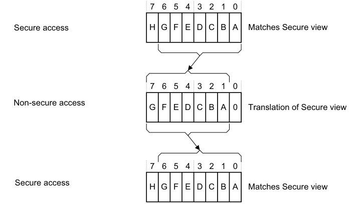
Image text
7 6 5 4 3 2 1 0
Secure access H G F E D C B A Matches Secure view
7 6 5 4 3 2 1 0
Non-secure access
G F E D C B A 0 Translation of Secure view
7 6 5 4 3 2 1 0
Secure access
H G F E D C B A Matches Secure view
Figure 4-9 shows how software reads of the interrupt priorities from Secure and Non-secure accesses relate to the priority values held in the Distributor, and to the interrupt values that are visible to Secure and Non-secure accesses. Figure 4-9 applies to a GIC that implements the maximum range of priority values.
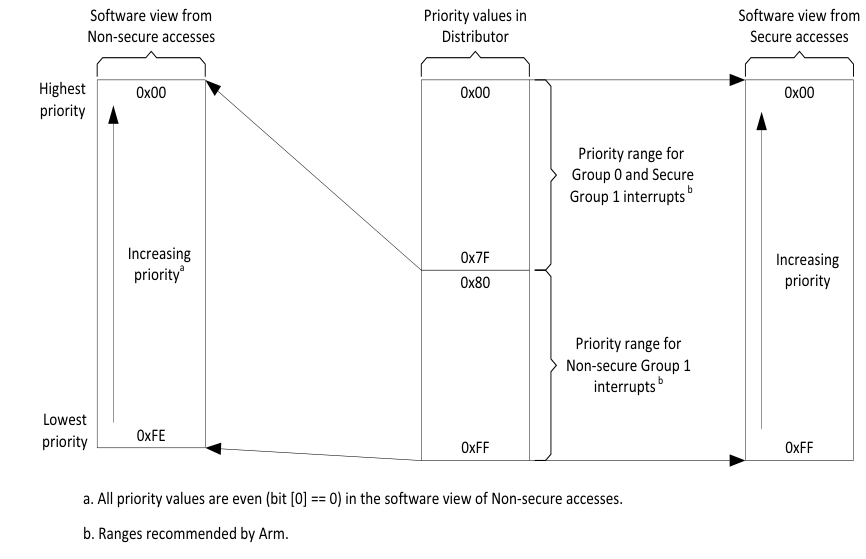
Image text
Software view from Priority values in Software view from
Non-secure accesses Distributor Secure accesses
Highest 0x00 0x00 0x00
priority
Priority range for
Group 0 and Secure
Group 1 interrupts [ b]
Increasing 0x7F Increasing
priority [a] 0x80 priority
Priority range for
Non-secure Group 1
interrupts [ b]
Lowest
0xFE
priority 0xFF 0xFF
a. All priority values are even (bit [0] == 0) in the software view of Non-secure accesses.
b. Ranges recommended by Arm.
Table 4-14 shows how the number of priority value bits implemented by the GIC affects the Secure and Non-secure reads of the priority of a Non-secure Group 1 interrupt.
Note Software executing in Non-secure state has no visibility of the priority settings of Group 0 interrupts, or where applicable, of Secure Group 1 interrupts.
Table 4-14 Effect of not implementing some priority field bits, two Security states
| Implemented priority bits, as seen by a Secure read [7:0] | Possible priority field values, for a Non-secure Group 1 interrupt Secure read Non-secure read | |—|— 0xFF-0x00(255-0), all values 0xFE-0x00(254-0), even values only | | [7:1] | 0xFE-0x00(254-0), even values only 0xFC-0x00(252-0), in steps of 4 | | [7:2] | 0xFC-0x00(252-0), in steps of 4 0xF8-0x00(248-0), in steps of 8 | | [7:3] | 0xF8-0x00(248-0), in steps of 8 0xF0-0x00(240-0), in steps of 16 |
This model for the presentation of priority values ensures software written to operate with an implementation of this GIC architecture functions as intended regardless of whether the GIC provides support for two Security states. However, programmers must ensure that software assigns the appropriate priority levels to the Group 0 and Group 1 interrupts.
Note To control priority values, Arm strongly recommends that:
- For a Group 0 interrupt, software sets bit[7] of the priority value field to 0.
- If using a Secure write to set the priority of a Non-secure Group 1 interrupt, software sets bit[7] of the priority value field to 1.
This ensures that all Group 0 and, if applicable, Secure Group 1 interrupts have higher priorities than all Non-secure Group 1 interrupts. However, a system might have requirements that cannot be met with this scheme.
Table 4-15 shows an example priority allocation scheme that ensures:
-
Some Group 0 interrupts have higher priority than any other interrupts.
-
Some Secure Group 1 interrupts have higher priority than any Non-secure Group 1 interrupt.
Table 4-15 Example priority allocation
| Interrupt security configuration | GICR_IPRIORITYR |
|---|---|
| Group 0 | 0b00 |
| Secure Group 1 | 0b01 |
| Non-secure Group 1 | 0b10 0b11 |
-
Software might not be aware that the GIC supports two Security states, and therefore might not know whether it is making Secure or Non-secure accesses to GIC registers. However, for any implemented interrupt, software can write 0xFF to the corresponding GICR_IPRIORITYR
priority value field, and then read back the value stored in the field to determine the supported interrupt priority range. Arm recommends that, before checking the priority range in this way: - For a peripheral interrupt, software first disables the interrupt.
-
For an SGI, software first checks that the interrupt is inactive.
4.8.7 Changing the priority of enabled PPIs, SGIs, and SPIs
If software writes to the GICD_IPRIORITYR